
77 Kensington Gardens, London W2 — a bespoke central spine staircase designed for a high-end townhouse in one of London's most prestigious addresses. A single 150×100mm RHS steel spine carrying 16 solid oak treads (120mm thick, 7 unique CNC-cut profiles), 10 toughened and laminated glass panels (17mm clear), a 40×40mm oak handrail, and integrated LED lighting beneath the upper landing. Floor-to-floor height: 3,890mm. This page documents the full design, specification, and component breakdown.
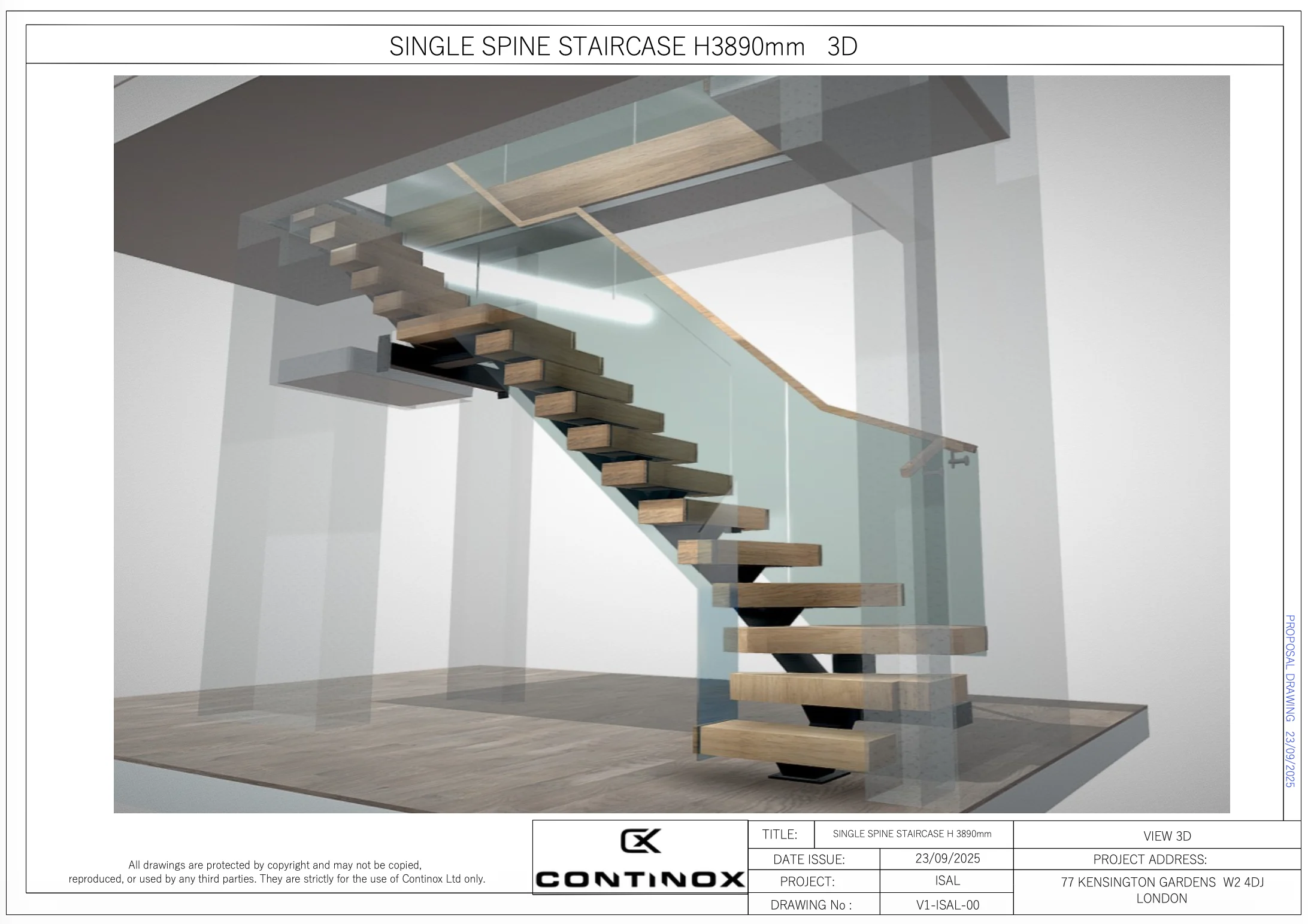
Single spine staircase — 150×100 RHS spine, 120mm solid oak treads, 17mm toughened laminated glass balustrade, 40×40 oak handrail
Client: Private homeowner — townhouse renovation. Location: 77 Kensington Gardens, London W2 4DJ. Scope: Design, fabrication and installation of a bespoke central spine staircase — single steel spine, solid oak treads, frameless glass balustrade, oak handrail, integrated LED lighting. Steel: 150×100×5mm RHS spine, 150×100×3mm RHS beam support, 6mm S275 tread mounting plates. Timber: 120mm thick solid oak — 16 treads (7 unique profiles) + 1 platform + 3 fascia boards + 40×40mm handrail. Glass: 17mm toughened and laminated clear glass — 10 panels (GP1–GP10). Compliance: Part K — 42° pitch, 216mm rise, 240mm going, 2,100mm headroom. Drawing package: V1-ISAL (proposal) + V3-ISAL (production), 19+ sheets.
The Brief — What the Client Needed
The client was renovating a period townhouse in Kensington Gardens and wanted a statement staircase to replace the existing traditional flight. The requirements were specific: a contemporary central spine design with the structural steelwork visible, solid oak treads thick enough to feel substantial (not thin veneered panels), frameless glass balustrade for maximum light transmission through the stairwell, and an oak handrail that felt warm and graspable — not a cold steel tube.
The floor-to-floor height of 3,890mm and the available plan footprint dictated a straight-flight configuration at 42° — the maximum pitch permitted under Part K for a domestic staircase. This made every millimetre of rise and going critical. The headroom clearance at the upper landing was tight at 2,100mm — exactly on the Part K minimum — which required precise coordination between the spine height, tread thickness, and landing beam position.
The Design — Anatomy of the Staircase
1 Central spine
The structural backbone of the staircase — a single 150×100×5mm RHS (rectangular hollow section) running the full length of the flight at 42°. This carries the entire load: 16 oak treads, the glass balustrade, the handrail, and all live loading. The spine is welded to a base plate at ground level (750×274mm, 6-bolt fixing to the concrete slab) and connects at the top to a 150×100×3mm RHS beam support that transfers the load into the upper floor structure.
Tread mounting plates (6mm S275 steel) are welded to the spine at 216mm rise intervals — each plate pre-drilled to accept the oak treads from above. The mounting plates are concealed beneath the treads once installed, with fixing caps covering the bolt heads for a clean finish.
2 Oak treads
16 solid oak treads at 120mm thickness — substantially thicker than the 40–50mm typical of standard oak staircase treads. The additional mass gives each tread a visual weight that matches the scale of the steel spine, and provides the structural depth needed to span from the central spine to the glass balustrade fixing points without deflection.
The tread package includes 7 unique profiles, each drawn as individual DXF files for CNC routing. T2 is the standard tread (750×267mm, quantity 10). The remaining 6 profiles are one-offs: T1 is the bottom tread with a wider approach, T3 is the top tread with an angled return, T4 and T5 are shaped treads at the quarter-turn, T6 is the wider landing-approach tread (910×468mm), and T7 is a rectangular tread at the upper transition. The platform (775×750mm) sits at the top of the flight where the staircase meets the upper floor.
Why 120mm oak? At this thickness, each tread weighs approximately 12–15kg. That mass eliminates the hollow drum-like resonance that thinner treads produce underfoot — a common complaint with budget floating staircases. The 120mm depth also means the treads can be profiled with angled cuts (T4 and T5 have compound angles of 53.9° / 78.4° and 126.1° / 117.2°) without losing structural integrity at the thin edge.
3 Glass balustrade
10 individual glass panels (GP1–GP10) in 17mm toughened and laminated clear glass, running the full length of the flight from ground to upper landing. Each panel is a unique shape — cut to follow the pitch of the staircase with the top edge parallel to the handrail and the bottom edge following the tread nosing line. The panels are point-fixed to the steel spine and tread mounting structure.
17mm laminated glass (rather than 10mm toughened) was specified for two reasons: the panels are the primary guarding barrier at height, and the laminated construction means that if a panel is damaged, it cracks but holds together rather than collapsing — critical at a floor-to-floor height of nearly 4 metres. For the full specification of glass types and when to use each, see our glass balustrade product page.
4 Oak handrail
40×40mm solid oak handrail — graspable, warm to the touch, and visually consistent with the oak treads. The handrail runs continuously from the bottom newel to the upper landing, with two wall-mounted brackets at the top where the handrail transitions to the landing. The 40×40mm section sits within the 32–50mm graspable diameter range recommended by Part K and Part M.
5 LED lighting
Integrated LED strip lighting beneath the upper landing beam, casting a wash of light down the glass balustrade and across the upper treads. The lighting is recessed into the underside of the beam support to avoid visible fittings — the effect is a soft glow that illuminates the stairwell without creating glare or harsh shadows on the treads. For more on staircase LED lighting options, see our LED staircase lighting guide.
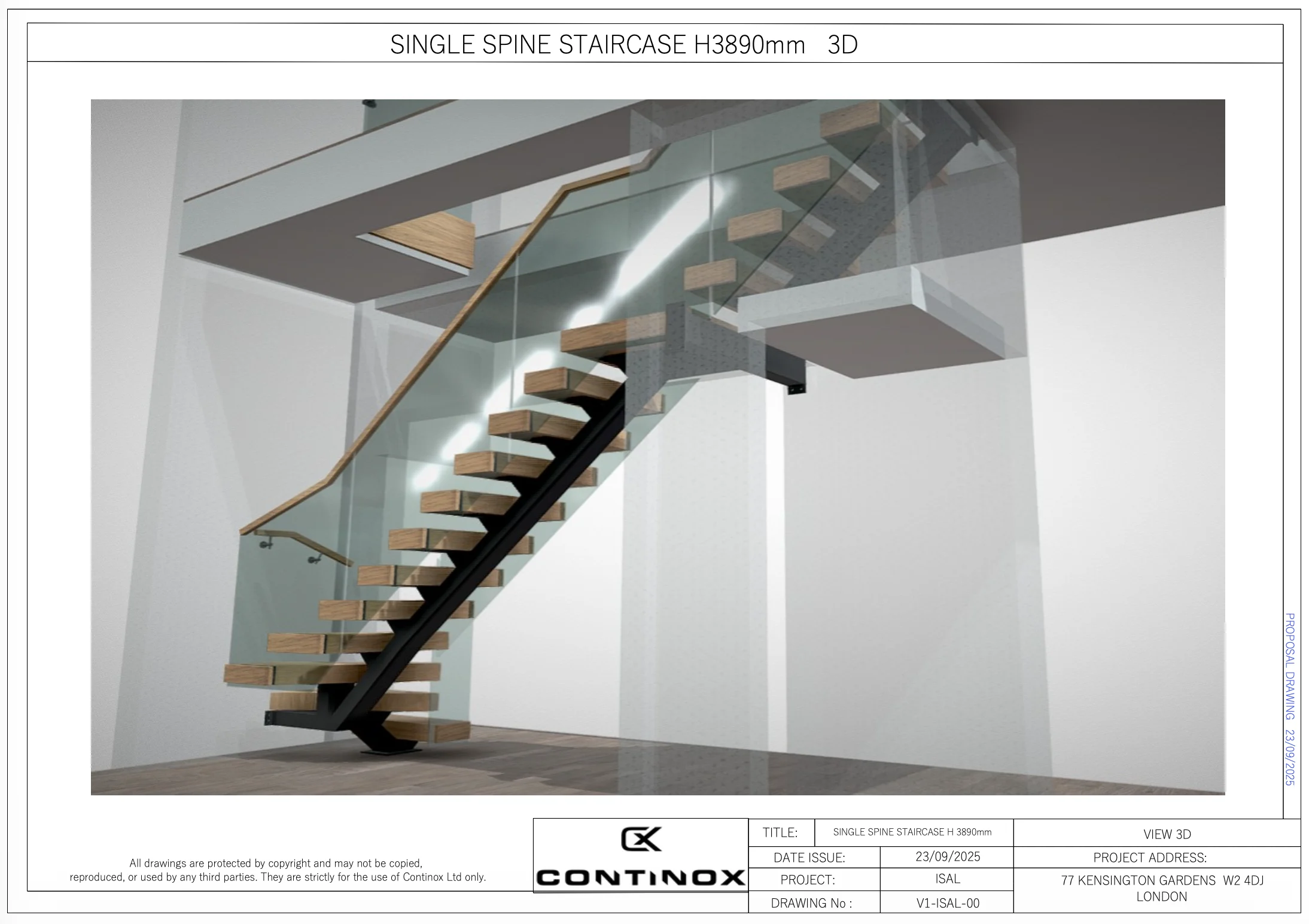 Rear view — LED lighting beneath landing beam, glass balustrade, oak handrail
 Component breakdown — spine, beam support, tread plates, glass panels, oak handrail
 Glass panel layout — 10 unique panels (GP1–GP10), 17mm toughened laminated
 Oak tread DXF profiles — T1 to T7, 7 unique shapes for CNC routing
Technical Specification — Materials & Dimensions
| Component | Specification | Detail |
|---|---|---|
| Central spine | 150×100×5mm RHS | Single spine — full flight length at 42° |
| Beam support | 150×100×3mm RHS | Upper landing — transfers load to floor structure |
| Tread mounting plates | 6mm S275 steel | Welded to spine at 216mm rise intervals |
| Oak treads | 120mm solid oak | 16 treads (7 unique DXF profiles) — CNC routed |
| Oak platform | 120mm solid oak | 775×750mm — top landing |
| Oak fascia boards | Solid oak | QTY: 3 — spine cladding |
| Glass panels | 17mm toughened laminated | 10 unique panels (GP1–GP10) — clear |
| Handrail | 40×40mm solid oak | Continuous, graspable — QTY: 2 lengths |
| Handrail brackets | Wall mount | QTY: 2 — upper landing transition |
| Tread cover caps | Steel | QTY: 25 — conceals bolt fixings |
| Rise | 216mm | Consistent across all 16 steps |
| Going | 240mm | Part K compliant (min 220mm) |
| Pitch | 42.0° | Part K maximum for domestic (42°) |
| Tread overlap | 27mm | Nosing projection over tread below |
| Floor-to-floor height | 3,890mm | FFL 0.00mm to FFL 3,890mm |
| Headroom | 2,100mm | Part K minimum (2,000mm) — met with 100mm margin |
Fabrication — How We Built It
Steel spine
The central spine was fabricated from a single length of 150×100×5mm RHS, cut to the precise angle and length required to span from the base plate to the beam support. Tread mounting plates (6mm S275) were welded to the spine at exactly 216mm vertical intervals — the consistency of this spacing is critical, because any variation produces an uneven rise that the user feels underfoot. We used a jig built from the production drawings to position each plate before welding.
Oak treads
Each of the 7 unique tread profiles was drawn as a DXF file (drawing V3-ISAL-16) and CNC-routed from 120mm solid oak blanks. The compound angles on T4 and T5 (the quarter-turn treads) required 5-axis routing to achieve the precise geometry. All treads were sanded to 180 grit, oiled, and pre-drilled for the mounting bolt positions before delivery to site.
Glass panels
The 10 glass panels were templated from the production drawings (V3-ISAL-19) and cut to shape by our glass supplier from 17mm toughened and laminated stock. Each panel is unique — following the pitch of the staircase with angled top and bottom edges. Bolt hole positions were drilled before toughening (you cannot drill toughened glass after processing). The panels were delivered to site in sequence (GP1 bottom, GP10 top) for installation in order.
 Side elevation (View A) — 42° pitch, 3,890mm floor-to-floor, 2,100mm headroom
 Exploded parts — spine, 16 treads, platform, 10 glass panels, fascia, handrail, caps
Compliance — Regulations & Standards
| Requirement | Standard | How We Met It |
|---|---|---|
| Maximum pitch | 42° (Part K) | Staircase designed at exactly 42.0° |
| Maximum rise | 220mm (Part K) | Rise: 216mm — within limit |
| Minimum going | 220mm (Part K) | Going: 240mm — exceeds minimum |
| Minimum headroom | 2,000mm (Part K) | Headroom: 2,100mm — 100mm above minimum |
| Guarding height | 900mm (Part K, domestic) | Glass panels provide guarding to full height |
| Handrail height | 900–1,000mm (Part K) | Oak handrail at 900mm above pitch line |
| Handrail graspable diameter | 32–50mm | 40×40mm oak section — within range |
| Glass specification | BS EN 12150 / BS EN 14449 | 17mm toughened and laminated — safety glass |
| 2R+G comfort check | 550–700mm | 2(216) + 240 = 672mm — within range |
Tight headroom note: At 3,890mm floor-to-floor with a 42° pitch, the available headroom at the upper landing was exactly 2,100mm — just 100mm above the Part K minimum of 2,000mm. This was identified during the proposal stage (drawing V1-ISAL-01) and highlighted in red on the side elevation. The beam support position was adjusted by 40mm to achieve the required clearance without compromising the landing structure. This is the kind of detail that gets missed without full production drawings — and the kind that fails a Building Control inspection if it's wrong.
Project Data — At a Glance
| Item | Detail |
|---|---|
| Project | ISAL — Single Spine Staircase H3890mm |
| Location | 77 Kensington Gardens, London W2 4DJ |
| Client type | Private homeowner — townhouse renovation |
| Staircase type | Central spine — single 150×100 RHS |
| Floor-to-floor | 3,890mm |
| Rise / Going / Pitch | 216mm / 240mm / 42.0° |
| Treads | 16× solid oak (120mm thick, 7 unique DXF profiles) |
| Platform | 1× solid oak (775×750×120mm) |
| Glass | 10× panels — 17mm toughened laminated clear |
| Handrail | 40×40mm solid oak — 2 lengths + 2 wall brackets |
| Fascia | 3× solid oak boards |
| Drawing package | V1-ISAL (proposal, 3 sheets) + V3-ISAL (production, 16+ sheets) |
| Designed & fabricated by | Continox Ltd, Portsmouth |
For more central spine staircase projects and pricing, see our bespoke staircase product page. Central spine staircases with glass balustrade start from £9,500. For a full pricing breakdown, see our bespoke staircase cost guide.
Want a Central Spine Staircase for Your Home?
Continox designs, fabricates and installs bespoke central spine staircases — steel, oak, glass, LED. Every project is drawn in full 3D, fabricated in-house, and installed by our own team. Based in Hampshire, working UK-wide. Free quote within 24 hours.