
Haccups Lane, Romsey — a bespoke L-shape floating staircase designed for a residential property in Hampshire. Steel central spine powder coated RAL 9005 jet black, 12 solid oak treads at 100mm thickness, a 3-piece oak quarter-turn platform with routed LED lighting channels, 12mm toughened clear glass balustrade, and a 40×40mm black handrail. This project went from proposal drawing to completed installation entirely in-house — design, steel fabrication, oak preparation, glass specification, and on-site fit. This page documents everything: the design decisions, the components, the fabrication process, and the installation.
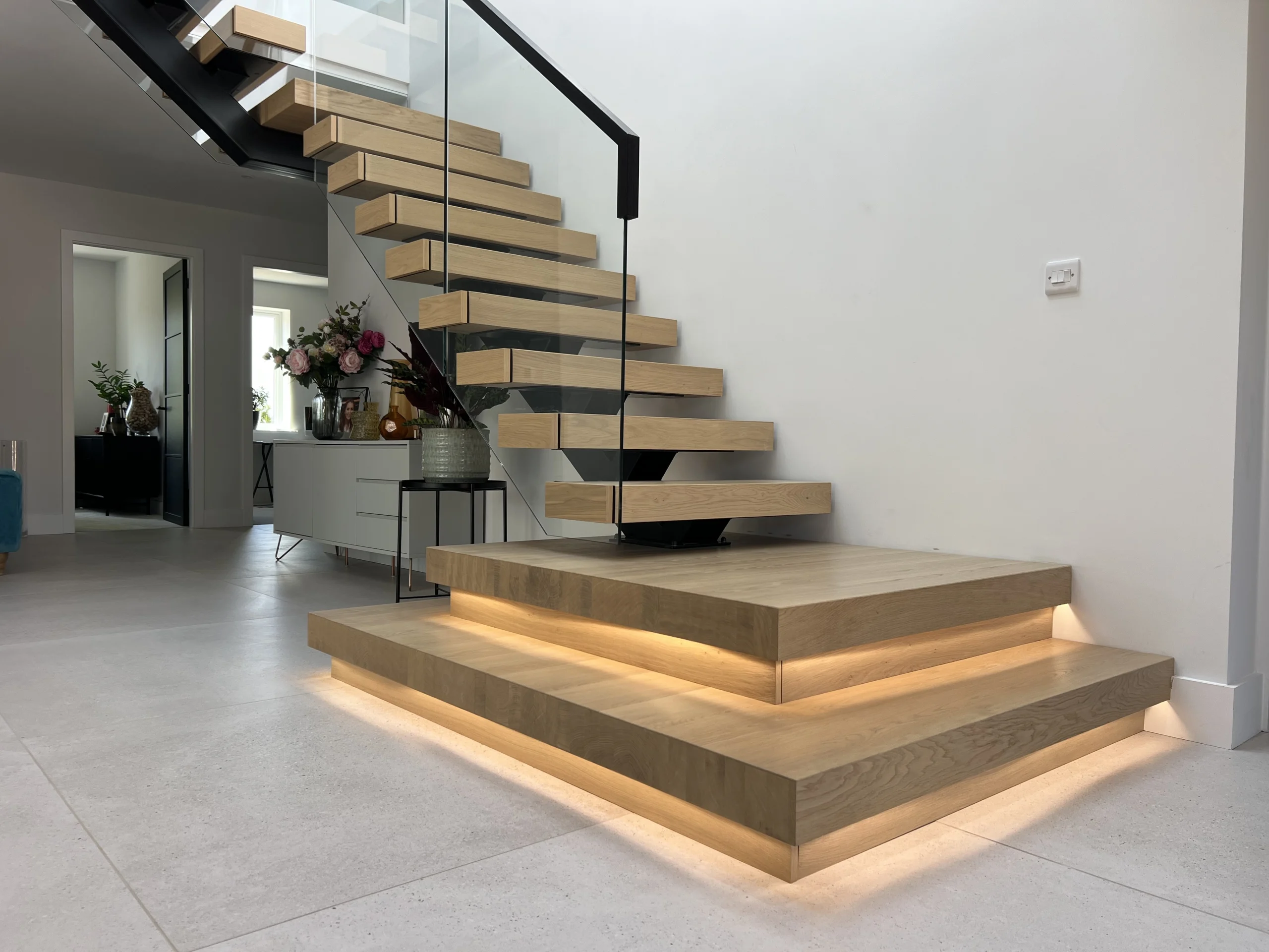
Completed L-shape floating staircase — RAL 9005 steel spine, 100mm solid oak treads, 12mm toughened glass balustrade, LED-lit oak platform
Client: Private homeowner — residential renovation. Location: Haccups Lane, Romsey, Hampshire SO51 0NP. Scope: Design, fabrication, and installation of a bespoke L-shape floating staircase with quarter-turn platform. Steel: Central spine with tread supports (TS1, TS2), wall brackets (B1–B4), posts (P1, P2), mounting plates (MP1–MP3), platform frame — all powder coated RAL 9005 jet black. Timber: 12× solid oak treads (900×275×100mm), 3-piece oak quarter-turn platform with LED groove, fascia boards (20mm oak), 14× end caps. Glass: 12mm toughened clear glass balustrade. Handrail: 40×40mm black. Compliance: Part K — 197mm rise, 245mm going, 38.8° pitch, 2,000mm headroom. Drawing package: V4.1-ISR-01 to V4.1-ISR-07.
The Brief — What the Client Needed
The homeowner was renovating a property in Romsey and wanted to replace a dated enclosed timber staircase with an open, contemporary floating design. The stairwell had an L-shape configuration — the staircase needed to rise straight, turn 90° at a quarter-turn platform, and continue to the upper floor. The key requirements: the steelwork had to disappear visually (jet black powder coat against a dark background), the oak had to feel solid and substantial, and the glass balustrade had to let maximum light into the hallway below.
The floor-to-floor height of 2,950mm with the available footprint produced a 38.8° pitch — comfortably under the Part K maximum of 42°, which gives a noticeably gentler climb than a staircase at the regulatory limit. The rise of 197mm and going of 245mm put the 2R+G comfort calculation at 2(197) + 245 = 639mm — right in the sweet spot of the 550–700mm range.
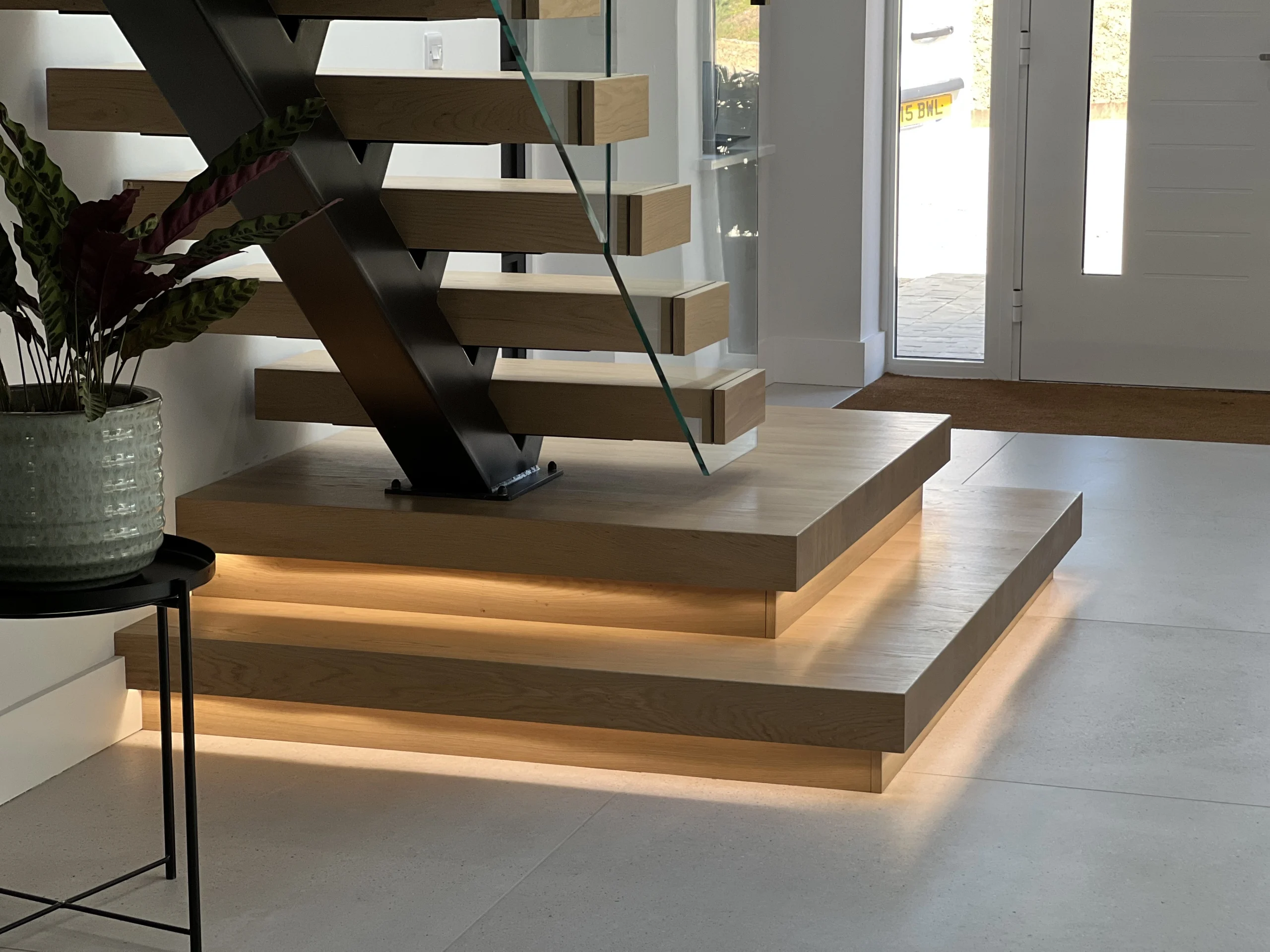
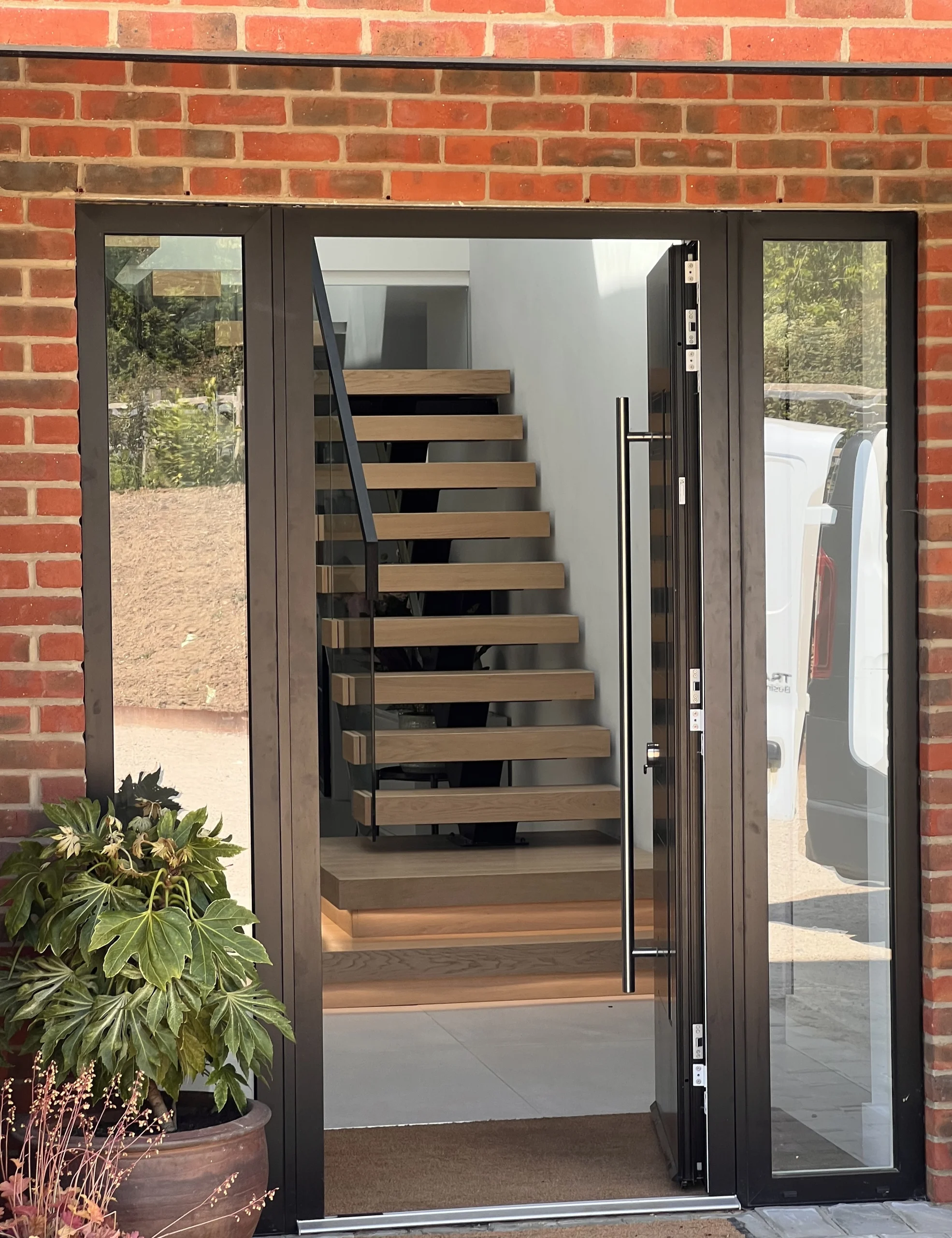 Entrance view — the staircase as you walk into the hallway
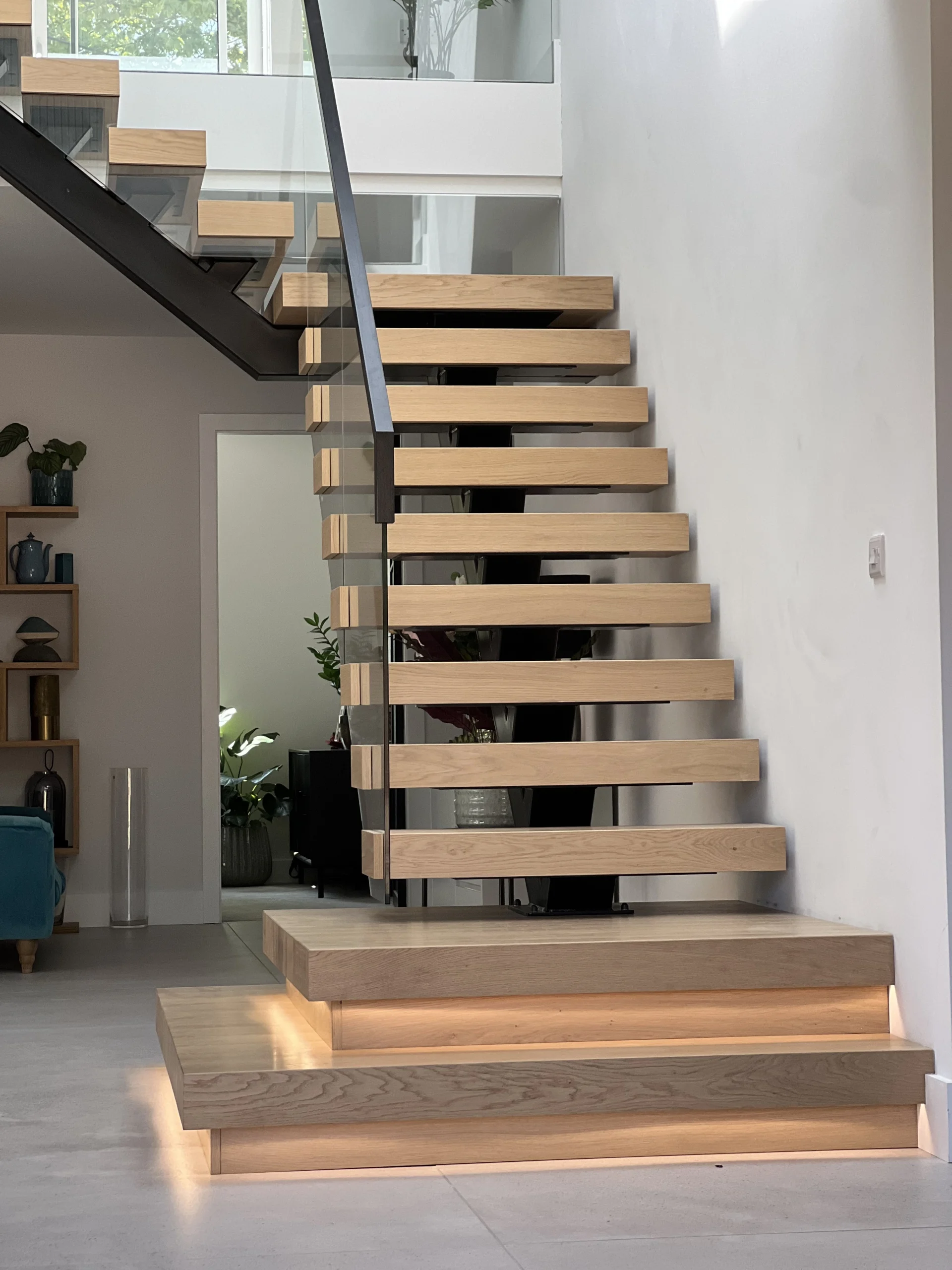 Front view — steel spine, oak treads, glass balustrade, black handrail
The Design — Every Component
1 Steel spine & structure
The structural backbone is a steel central spine running the full length of the lower flight, with tread support brackets (TS1) welded at 197mm rise intervals on both sides. Each tread sits on a pair of TS1 brackets — cantilevered from the spine on the open side, and supported by wall brackets (B1–B4) on the wall side. The spine connects at the bottom via mounting plate MP1 to the ground floor slab, and at the quarter-turn to the platform frame via MP2 and MP3 connections.
The platform frame is a separate welded steel assembly — a rectangular frame that supports the three oak platform pieces and transfers load into the walls at the corner. The upper flight uses the same bracket system to carry the remaining treads from the platform to the upper floor.
Everything steel was powder coated RAL 9005 jet black before delivery to site. The satin black finish absorbs light and recedes visually — the eye reads the staircase as floating oak treads and glass, with the steel structure disappearing into the background.
 Central spine — RAL 9005 jet black, tread support brackets visible
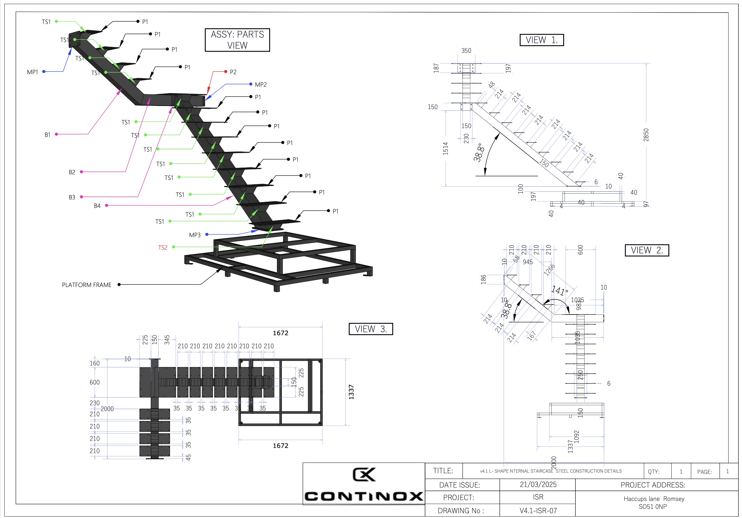 Production drawing — spine assembly, wall brackets, platform frame dimensions
2 Oak treads & platform
12 solid oak treads at 900×275×100mm — each one identical, cut from the same batch of kiln-dried oak for consistent colour and grain. At 100mm thickness, the treads have a substantial visual presence and provide the structural depth to span from the spine bracket to the glass fixing point without perceptible flex underfoot.
The quarter-turn platform is the design centrepiece — a 3-piece oak assembly that wraps around the corner of the L:
Platform 2.1 (900×980×100mm) — the landing at the top of the lower flight. Platform 2.2 (1,818×1,410×100mm) — the main L-shape platform, the largest single oak element in the project. Platform 2.3 (1,328×1,165×100mm) — the transition to the upper flight, with a CNC-routed LED groove along the front edge for integrated under-platform lighting.
Below the oak platforms, fascia boards (20mm oak) clad the steel platform frame from below — Platform 3.1 (1,115×1,228mm) and Platform 3.2 (1,360×1,718mm). These conceal the steelwork completely when viewed from the ground floor, so the underside of the platform reads as a continuous oak surface rather than exposed steel.
End caps: Every tread has an oak end cap (275×100×20mm, detail 4.2, QTY: 13) that covers the exposed end grain where the tread meets the open side of the staircase. The bottom tread has a slightly smaller cap (225×100×20mm, detail 4.1, QTY: 1) to match the narrower profile. These are small details — but they're the difference between a staircase that looks finished and one that looks like it's still waiting for the joiner.
 100mm solid oak treads — end caps fitted, bolt fixings concealed
 3-piece oak platform — LED groove illuminated, fascia boards below
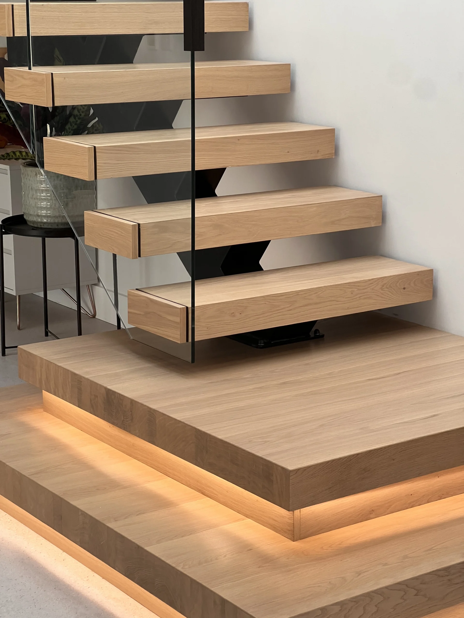 Lower flight meeting the quarter-turn platform — seamless oak transition
 Production drawing — tread 900×275×100mm, platform detail, end caps, assembly breakdown
3 Glass balustrade & handrail
12mm toughened clear glass panels running the full length of the open side — from the bottom tread, up through the quarter-turn, to the upper landing. The glass provides the guarding barrier required by Part K while maintaining full visual transparency through the stairwell. Light from the upper floor and the platform LEDs passes through the glass unobstructed, keeping the hallway below bright.
The handrail is a 40×40mm section in black — matching the RAL 9005 steelwork rather than the oak. This was a deliberate design choice: the black handrail reads as a continuous line from the steel spine up through the glass to the upper landing, tying the steel and glass elements together visually. End caps finish the handrail terminations cleanly.
 Upper landing — 12mm toughened glass balustrade, 40×40mm black handrail
 Full specification — 3D view, plan, sections, all dimensions annotated
4 LED platform lighting
LED strip lighting is recessed into a CNC-routed groove along the front edge of Platform 2.3. The groove is cut into the underside of the oak at a precise depth that conceals the LED strip from direct view — you see the light wash, not the source. The effect illuminates the upper treads and the glass balustrade from above, creating a warm ambient glow at night without needing overhead stairwell lighting.
This is an increasingly popular feature on our floating staircases — for more on how we integrate LED lighting into oak and steel staircase designs, see our floating staircases with LED lighting guide.
Installation — From Steel Frame to Finished Staircase
The installation followed a specific sequence designed to minimise time on site and protect finished surfaces:
1 Steel spine & platform frame
The steel spine and platform frame were installed first — bolted to the ground floor slab, fixed to the walls via brackets B1–B4, and levelled precisely before tightening. This is the structural skeleton that everything else attaches to. At this stage the staircase looks like raw black steelwork — functional but not finished.
2 Oak platforms & fascia
The three oak platform pieces were lifted into position on the steel frame and bolted down. Fascia boards were fitted below to clad the steel. LED strip was installed in the routed groove before the platform was secured — you can't access the groove afterwards.
3 Oak treads & end caps
Treads were fitted from bottom to top, bolted to the TS1 brackets through pre-drilled holes. End caps were glued and pinned to cover the exposed tread ends. Cover caps were pressed into the bolt holes for a clean finish.
4 Glass & handrail
Glass panels were fitted last — point-fixed through pre-drilled holes, with the handrail mounted on top. Fitting glass last protects the panels from damage during the oak and steel installation.
 Step 1 — Steel spine and platform frame installed
 Step 2 — Oak platforms fitted onto steel frame
Complete — treads, glass, handrail, LED all fitted
Step 2 — Oak platforms fitted onto steel frame
Complete — treads, glass, handrail, LED all fitted
Technical Specification — Materials & Dimensions
| Component | Specification | Detail |
|---|---|---|
| Central spine | Steel — RAL 9005 | Full-length stringer with TS1/TS2 tread supports |
| Wall brackets | Steel — RAL 9005 | B1, B2, B3, B4 — bolted to masonry |
| Platform frame | Steel — RAL 9005 | Welded rectangular frame for quarter-turn platform |
| Posts | Steel — RAL 9005 | P1, P2 with MP1–MP3 mounting plates |
| Oak treads | 900×275×100mm | 12× solid oak — kiln-dried, oiled |
| Platform 2.1 | 900×980×100mm oak | Lower flight landing piece |
| Platform 2.2 | 1,818×1,410×100mm oak | Main L-shape platform — largest oak element |
| Platform 2.3 | 1,328×1,165×100mm oak | Upper transition — with CNC-routed LED groove |
| Fascia 3.1 | 1,115×1,228×20mm oak | Under-platform cladding (lower) |
| Fascia 3.2 | 1,360×1,718×20mm oak | Under-platform cladding (upper) |
| End caps | 275×100×20mm oak | 13× tread end caps + 1× bottom cap (225mm) |
| Glass balustrade | 12mm toughened clear | Full-length — BS EN 12150 compliant |
| Handrail | 40×40mm black | Continuous with end caps |
| LED lighting | LED strip in routed groove | Platform 2.3 — under-edge illumination |
| Rise | 197mm | × 15 risers — consistent throughout |
| Going | 245mm | Part K compliant (min 220mm) |
| Pitch | 38.8° | Under Part K max (42°) |
| Floor-to-floor | 2,950mm | FFL to FFL |
| Headroom | 2,000mm | Part K minimum — verified on site |
Compliance — Regulations & Standards
| Requirement | Standard | How We Met It |
|---|---|---|
| Maximum pitch | 42° (Part K) | Designed at 38.8° — 3.2° under limit |
| Maximum rise | 220mm (Part K) | Rise: 197mm — 23mm under limit |
| Minimum going | 220mm (Part K) | Going: 245mm — 25mm over minimum |
| Minimum headroom | 2,000mm (Part K) | Headroom: 2,000mm — on the minimum, verified |
| Guarding height | 900mm (Part K, domestic) | Glass balustrade to 900mm+ above pitch line |
| 2R+G comfort check | 550–700mm | 2(197) + 245 = 639mm — ideal range |
| Glass specification | BS EN 12150 | 12mm toughened clear — safety glass |
| Surface finish | BS EN 13438 | Polyester powder coat RAL 9005 |
Headroom note: The headroom at the lower flight measured exactly 2,000mm — the Part K minimum. This was identified during the proposal stage (drawing V4.1-ISR-01) and confirmed on site before fabrication. At 2,000mm there is zero margin — any variation in floor-to-floor height, slab thickness, or ceiling finish could push the headroom below the legal minimum. We measured the site three times before committing to fabrication. This is why full production drawings and a site survey matter — a staircase ordered from catalogue dimensions cannot account for this level of tolerance.
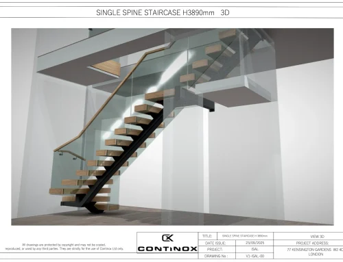
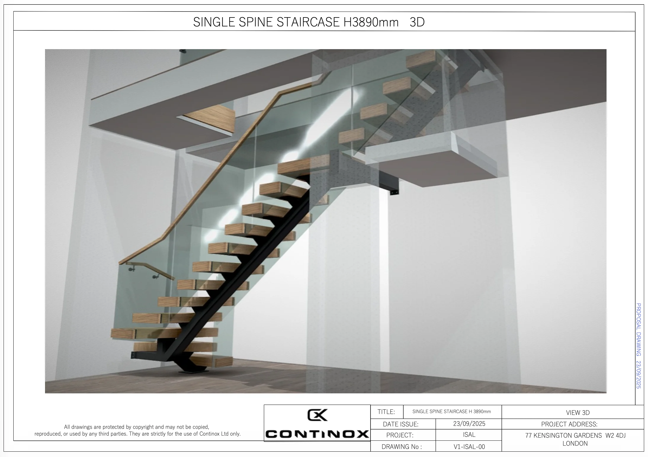
 3D proposal model — how the staircase was presented before fabrication began
 Production drawings — 3-piece platform, fascia boards, LED groove, steel frame
Project Data — At a Glance
| Item | Detail |
|---|---|
| Project | ISR — V4.1 L-Shape Internal Staircase |
| Location | Haccups Lane, Romsey, Hampshire SO51 0NP |
| Client type | Private homeowner — residential renovation |
| Staircase type | L-shape floating — quarter-turn with platform |
| Floor-to-floor | 2,950mm |
| Rise / Going / Pitch | 197mm / 245mm / 38.8° |
| Treads | 12× solid oak (900×275×100mm) |
| Platform | 3-piece solid oak with LED groove + steel frame |
| Glass | 12mm toughened clear — full-length balustrade |
| Steel finish | Powder coated RAL 9005 jet black |
| Drawing package | V4.1-ISR-01 to V4.1-ISR-07 (proposal + production) |
| Designed & fabricated by | Continox Ltd, Portsmouth |
For more floating staircase projects and pricing, see our bespoke staircase product page. L-shape floating staircases with glass balustrade start from £9,500. For a full pricing breakdown, see our bespoke staircase cost guide.
Want a Floating Staircase Like This One?
Continox designs, fabricates and installs bespoke floating staircases — steel, oak, glass, LED. Straight flights, L-shapes, half-turns. Every project drawn in full 3D, fabricated in-house, installed by our own team. Based in Hampshire, working UK-wide. Free quote within 24 hours.